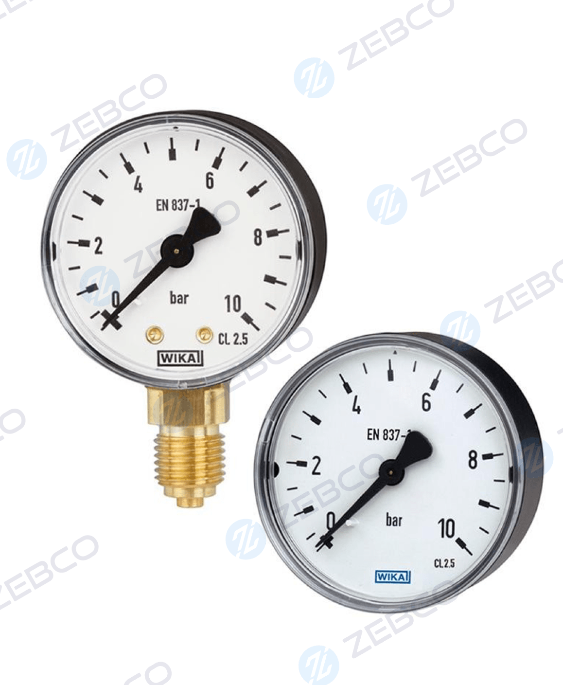
Wika Bourdon Tube Pressure Gauge, Copper Alloy ( Model: 111.10, 111.12 )
At Zebco Engineering, we are a reliable supplier & exporter of Wika Bourdon Tube Pressure Gauges (Copper Alloy – Models 111.10, 111.12), made for accurate & steady performance in industrial use.

- Reliable and cost-effective
- Design per EN 837-1 or ASME B40.100
- Nominal size 40 [1 ½] 50 [2] 63 [2 ½] 80 [3] 100 [4] and 160 [6]
- Scale ranges to 0 ... 400 bar [0 ... 6,000 psi]
Application of Bourdon Tube Pressure Gauge Copper Alloy
- For gaseous and liquid aggressive media that are not highly viscous or crystallising, also in aggressive environments
- Pneumatics
- Heating and air-conditioning technology
- Medical engineering
Descriptions ( Bourdon Tube Pressure Gauge, Copper Alloy )
The model 111 pressure gauges are based on the proven Bourdon tube measuring system. The deflection of the Bourdon tube is transmitted to a movement and indicated.
The modular design enables a multitude of combinations of case materials, process connections, nominal sizes and scale ranges. Due to the high variance, the instrument is suitable for use in a wide range of applications within industry.
For mounting in control panels, the pressure gauges can, depending on the process connection, be fitted with a surface mounting flange or with a triangular profile ring and mounting bracket.
The standard version of the model 111 is manufactured, cost-optimised on modern production lines, in volumes of several million instruments per year.
Specifications
| Standard |
| |
| Further version |
| |
| Nominal size (NS) |
| |
| Connection location |
| |
| Window |
| |
| Case | - | |
| Design |
| |
| Material |
| |
| Ring |
| |
| Mounting |
| |
| Movement |
| |
Let’s Get Started
Our team is here to help with all your industrial needs. Reach out to us today, and let Zebco Engineering provide the solutions you're looking for.


Need Expert Assistance?
Complete the Form and We'll Reach Out Soon!


